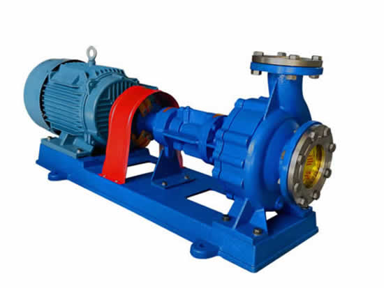
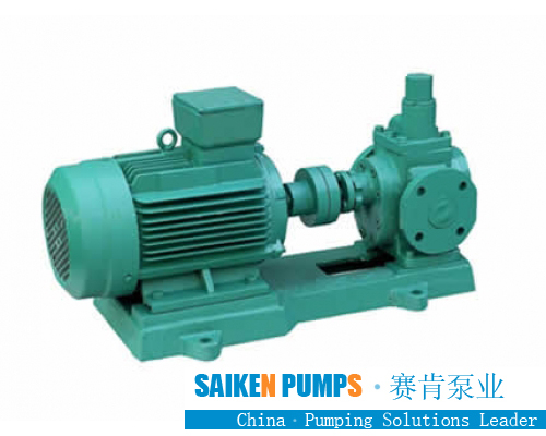
Working principle of gear pump manufacturers
The hydraulic station is also called hydraulic pump station. The motor drives the oil pump to rotate. The pump draws oil from the oil tank and converts the mechanical energy into the pressure energy of the hydraulic oil. The hydraulic oil is realized by the hydraulic valve through the manifold block (or valve combination). After the flow rate is adjusted, it is transmitted to the oil cylinder or oil motor of the hydraulic machinery through an external pipeline, thereby controlling the direction change of the hydraulic motor, the size of the force and the speed, and pushing various hydraulic machinery to do work.
The hydraulic station is an independent hydraulic device. It supplies oil according to the requirements of the driving device (host), and controls the direction, pressure and flow of the oil flow. It is suitable for various hydraulic machinery where the host and the hydraulic device are separable, and the motor drives the oil pump. When rotating, the pump sucks oil from the oil tank and then pumps oil, converting mechanical energy into pressure energy of hydraulic oil.
After the user purchases, as long as the hydraulic station is connected to the actuator (cylinder and oil motor) on the host with an oil pipe, the hydraulic machine can realize various prescribed actions and working cycles.
Gear pump factory structure installation
According to the mechanism and installation position of the pump device, it can be divided into:
1) Top-mounted vertical type: The pump device is installed vertically on the fuel tank cover and is mainly used for quantitative pump systems.
2) Top-mounted horizontal type: The pump device is installed horizontally on the fuel tank cover, mainly used for variable pump system to facilitate flow adjustment.
3) Side-mounted type: The pump device is horizontally installed on a separate foundation next to the fuel tank. The side-mounted type can be equipped with a spare pump. It is mainly used for systems with a large fuel tank capacity of 250 liters and a motor power of 7.5 kilowatts or more.
cooling method
1) Natural cooling: Cooling by heat exchange between the fuel tank itself and the air, generally used in systems with a fuel tank capacity of less than 250 liters.
2) Forced cooling: A cooler is used for forced cooling, generally used in systems with a fuel tank capacity greater than 250 liters. The hydraulic station takes the effective oil storage measurement of the oil tank and the motor power as the main technical parameters. There are 18 specifications of fuel tank capacity (unit: liter/L): 25, 40, 63, 100, 160, 250, 400, 630, 800, 1000, 1250, 1600, 2000, 2500, 3200, 4000, 5000, 6000 sets According to user requirements and operating conditions, the series hydraulic station can achieve: ①Configure integrated blocks according to the system, or without integrated blocks; ②Can be equipped with coolers, heaters, and accumulators; ③Can be equipped with electrical control devices, It is also possible to have no electrical control device.
Gear pump manufacturer oil tank form
1) Ordinary steel plate: The box body is welded by 5MM-6MM steel plate, and the panel is 10-12MM steel plate. If there are too many holes, it can be thickened or reinforced.
2) Stainless steel plate: The box body is made of 304 stainless steel plate with a thickness of 2-3mm, and the panel is made of 304 stainless steel plate with a thickness of 3-5mm.
3) It is difficult to realize the anti-rust treatment inside the ordinary steel oil tank. The rust entering the oil circulation system will cause many failures. The all-stainless steel design oil tank solves this industry problem.
structure type
1) Piston type
The single-rod hydraulic cylinder has a piston rod at only one end. As shown in the figure is a single-piston hydraulic cylinder. The inlet and outlet ports A and B at both ends can pass pressure oil or return oil to achieve two-way movement, so it is called a double-acting cylinder.
2) Plunger type
①The plunger hydraulic cylinder is a single-acting hydraulic cylinder, which can only achieve one direction of movement by hydraulic pressure, and the return stroke of the plunger depends on other external forces or the weight of the plunger;
②The plunger is only supported by the cylinder liner without contacting the cylinder liner, so that the cylinder liner is very easy to process, so it is suitable for long-stroke hydraulic cylinders;
③The plunger is always under pressure during operation, so it must have sufficient rigidity;
④The weight of the plunger is often large, and it is easy to sag due to its own weight when placed horizontally, causing unilateral wear of the seal and guide, so its vertical use is more advantageous.
3) Telescopic
Telescopic hydraulic cylinders have two-stage or multi-stage pistons. In the telescopic hydraulic cylinder, the order of extension of the pistons is from large to small, while the order of no-load retraction is generally from small to large. The telescopic cylinder can achieve a longer stroke, while the length when retracted is shorter, and the structure is more compact. This type of hydraulic cylinder is often used in construction machinery and agricultural machinery.
4) Swing type
Swing hydraulic cylinder is an executive element that outputs torque and realizes reciprocating motion, also called swing hydraulic motor. There are two forms of single blade and double blade. The stator block is fixed on the cylinder, and the blade and the rotor are connected together. According to the oil inlet direction, the blades will drive the rotor to reciprocate.
Secondary brakingedit
TY1S (B792S), B157, TE130 are used for 2JK, 2JK/A, 2JK/E single rope double drum series hoists.
TY1D (B792D), B159, TE131 are used for JK, JK/A, JK/E single-rope single-drum series hoists and JKM-C, JKMD-C, JKM-A, JKMD-A, JKM-E, JKMD- E-well tower type and floor type multi-rope hoist.
Hydraulic delay secondary brake hydraulic station:
TY3S (TK083S) and TE002 are used for single rope double drum series hoists (the hoist model is the same as above).
TY3D (BTK083D) and TE003 are used for single-rope monotube series hoists and multi-rope series (tower and floor) hoists (the hoist model is the same as above).
Component editing
Functional parts
The hydraulic station is composed of a pump device, integrated block or valve combination, oil tank, and electrical box. The functions of each component are as follows:
Pump device-equipped with a motor and an oil pump, it is the power source of the hydraulic station, which converts mechanical energy into the power energy of hydraulic oil.
Manifold-is a combination of hydraulic valve and channel body. It regulates the direction, pressure and flow of hydraulic oil.
Valve combination-the plate valve is installed on the vertical plate, and the pipe behind the plate is connected, which has the same function as the integrated block.
The oil tank is a semi-closed container welded with steel plate, and is also equipped with an oil filter, an air filter, etc., which are used for oil storage, oil cooling and filtration.
Electrical box-divided into two forms: one is equipped with a terminal board with external leads; the other is equipped with a full set of control appliances.
Components
⑴Motor, gear pump-provide driving force for hydraulic system.
⑵ Electromagnetic reversing valve-control the direction of hydraulic oil flow and change the direction of movement of the cylinder.
⑶ Electromagnetic relief valve-prevent the entire hydraulic system from overpressure, equivalent to a safety valve, protect the safety of the oil pump and the oil circuit system and keep the pressure of the hydraulic system constant.
⑷ Pressure reducing valve-by adjusting the pressure reducing valve, different working mechanisms can meet the requirements of different working pressures, so that the secondary oil circuit pressure is lower than the primary oil circuit pressure.
⑸ Speed control valve-throttle the oil circuit speed, which can change the working speed of the hydraulic cylinder of the actuator.
⑹Hydraulic oil filter——There are two oil filter ports in the hydraulic station. One is installed at the oil suction port of the gear pump to avoid sucking particles and other impurities in the hydraulic oil of the oil tank. The other is installed in the hydraulic oil delivery pipeline of the system to remove impurities in the hydraulic oil, and at the same time, it can also remove gums, asphaltenes, and carbonized particles produced by the chemical changes of the hydraulic oil itself. So as to prevent the valve core from jamming and the orifice clogging. The piping system is equipped with a differential pressure alarm device. When the filter element is clogged, an electric signal is sent out. At this time, the filter element should be cleaned or replaced.
⑺ Pressure gauge-used to display the working pressure of the hydraulic station to facilitate the operator to control the oil pressure.
⑻Air filter-installed on the fuel tank, it has three functions. One is to prevent pollutants in the air from entering the fuel tank; the other is to ventilate and avoid the pumping phenomenon; the third is to double as a hydraulic oil replenishment port.
⑼Oil level gauge-installed on the side of the oil tank to display the level of hydraulic oil.
⑽Temperature meter—Some oil tanks are equipped with a thermometer to display the temperature of hydraulic oil.


 +8617731766260/18233754501
  fan@saikenpumps.com


 +8617731766260/18233754501
 +86-317-8227664
 +8618233754501